This article is also published in many bookstores for the benefit of offline readers. The eBooks are DRM-free, while the printed editions compile multiple articles and feature original photography at full resolution.
You can find printed compilations here, and individual eBooks at Amazon Kindle, Apple Books, Kobo and other stores. The proceeds support the improvement of current articles and the development of new ones.
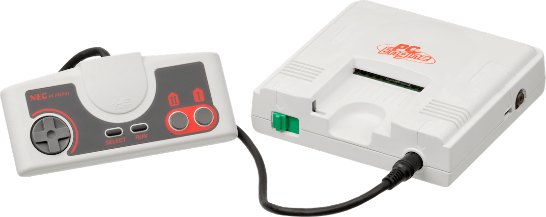
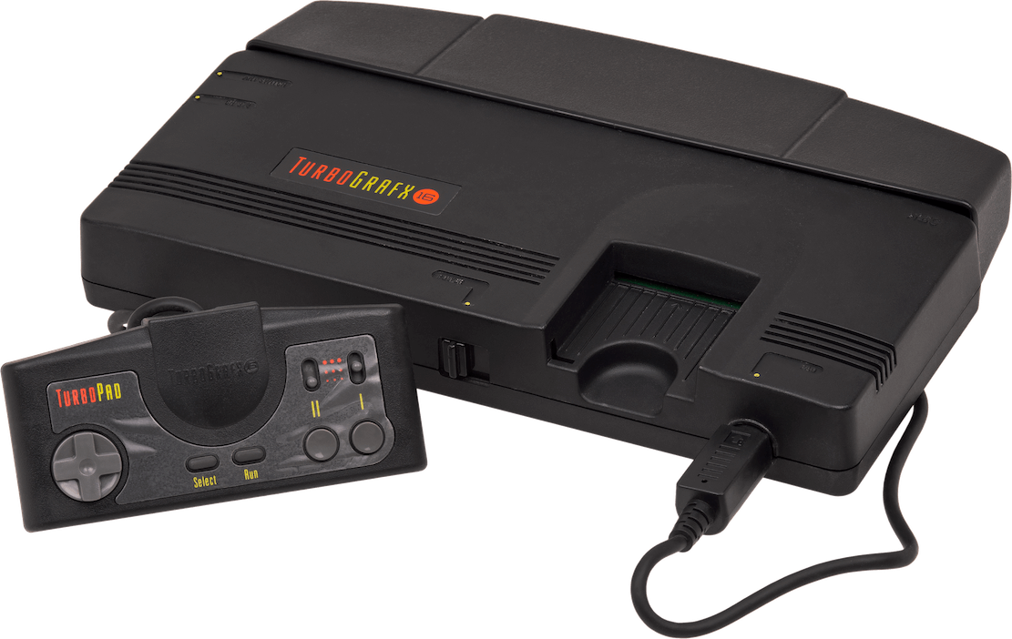
The PC Engine. Released on 30/10/1987 in Japan.The TurboGrafx-16. Released on 29/08/1989 in America, 22/11/1989 in France and 1990 in the UK and Spain.
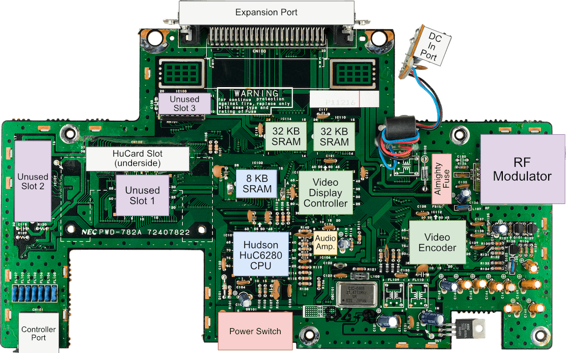
In a bold move, Hudson and NEC joined forces to pioneer the 4th generation of consoles. Unfortunately, their efforts were gradually overshadowed as the competition emerged. Nonetheless, their console remains one of the most compact designs of that era.
Models and variants
Just like the Master System, NEC shipped numerous adaptations and unusual variations, which can initially be difficult to follow. So, for future reference, here are the most significant models:
PC Engine: The first console featuring this architecture, but it was only released in Japan. It resembles a small white box with minimal ports.
TurboGrafx-16: A redesigned version of the PC Engine for the American market. It retains the same features, but with a different external appearance. This reminds me of the NES/Famicom adaptation.
Supergrafx: An enhanced version of the PC Engine with a completely different case and upgraded hardware. Its exclusive features are beyond the scope of this article.
PC Engine Duo/TurboDuo: A combination of the PC Engine/TurboGrafx and the aftermarket CD-ROM² expansion.
This article will focus on the PC Engine/TurboGrafx-16, but will also explore the expansions that culminated in the release of the PC Engine Duo/TurboDuo.
CPU
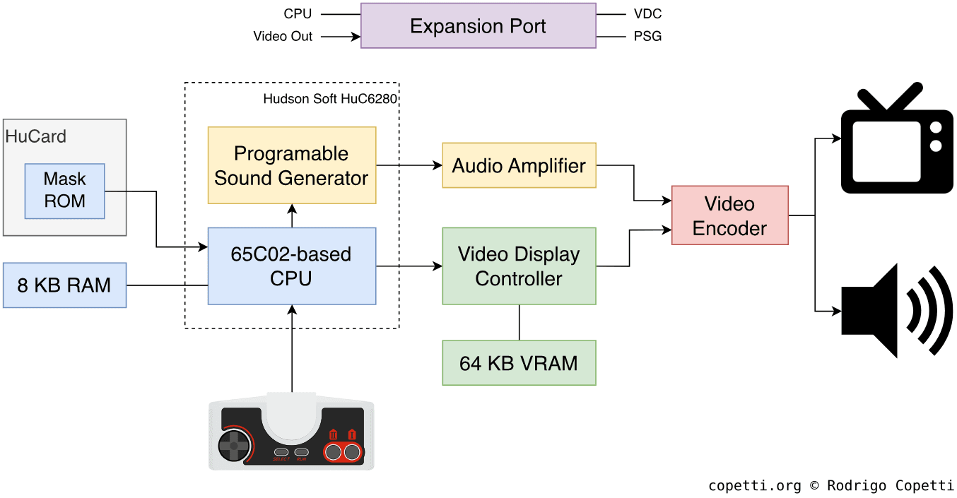
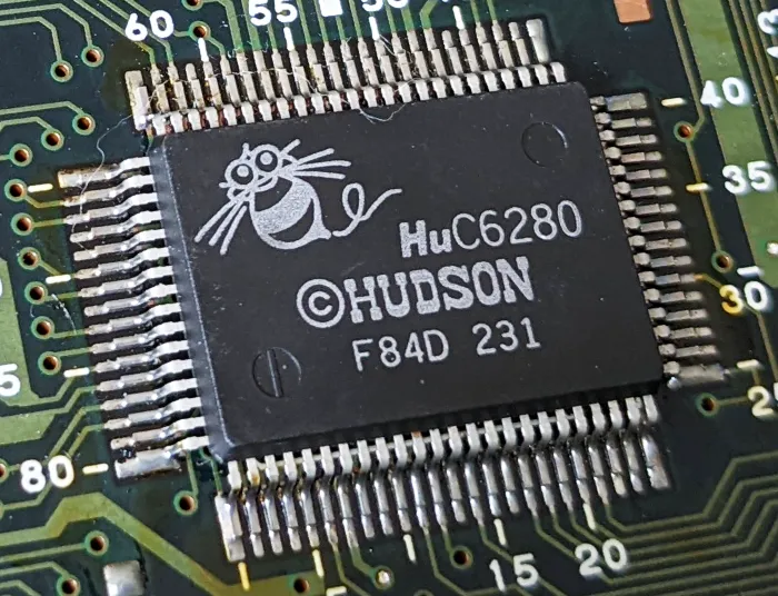
Inside this console, we find the HuC6280, a chip developed by Hudson Soft that integrates two components. One of them is the CPU, which can operate at two speeds: ~1.79 MHz and ~7.16 MHz.
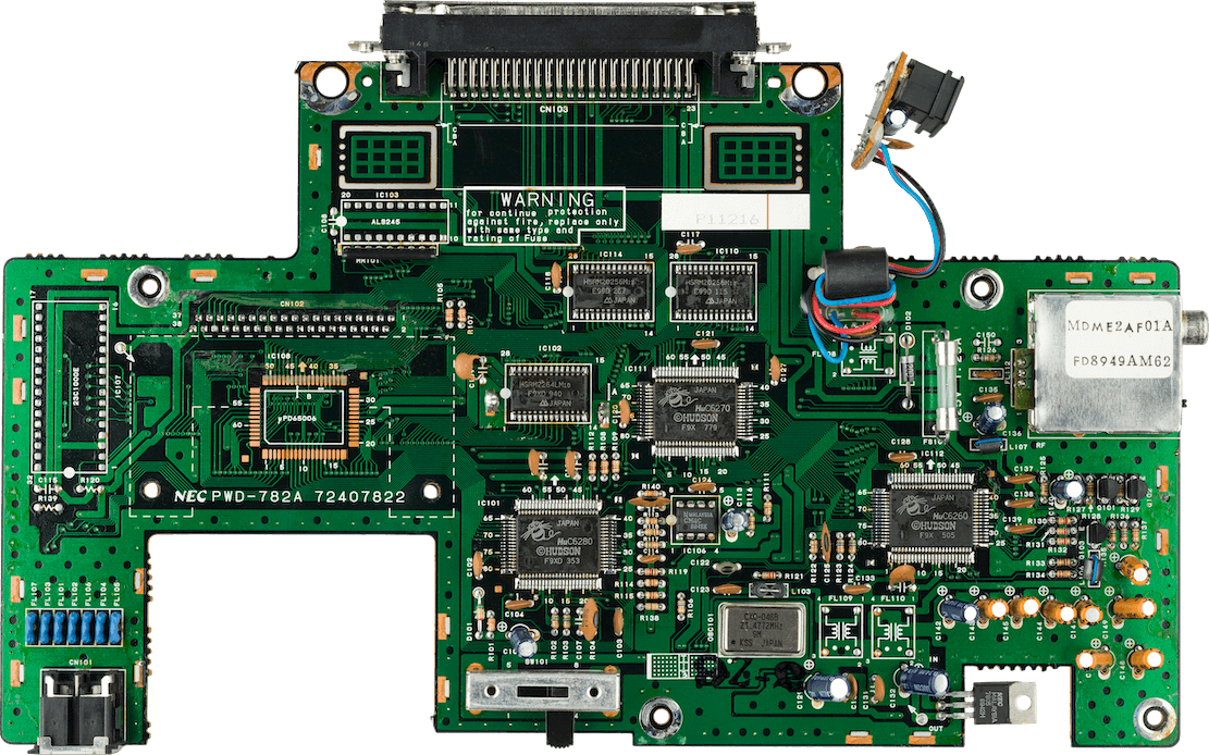
The HuC6280 chip on the PC Engine’s motherboard
The HuC6280 is not an off-the-shelf component, like the Z80; it is instead a proprietary CPU designed by NEC. Its specification seems to replicate much of the behaviour of the famous MOS 6502 and WDC’s 65C02. That being said, what does this mean for the programmer?
Before we start, I have already covered the MOS 6502 CPU in the NES article and described a 16-bit variant made by WDC and Ricoh in the SNES article, in case you wish to review them first.
The 65C02 is another modified version of the MOS 6502, made by Western Design Center (WDC). It is significantly more efficient due to its CMOS manufacturing approach. From the software perspective, the 65C02 introduces a handful of new instructions and modifies the behaviour of some existing ones [1].
While we could discuss more about the 65C02, I find it more relevant to focus on the features added by Hudson (which complement the 65C02), as they are critical to efficiently operate this console.
Additional opcodes, some of which target the components surrounding the CPU.
An 8-bit I/O port for interfacing with external components.
An interrupt controller to handle interrupts from other devices.
A timer, which counts down from a specified value and, upon completion, dispatches an interrupt to the CPU.
Finally, there are 8 KB of Random-Access Memory (RAM) available for general-purpose use.
Memory access
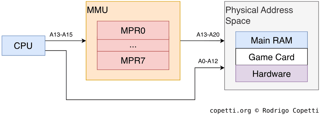
One aspect I have not yet mentioned is that NEC also added a Memory Management Unit (MMU) adjacent to the CPU, allowing it to handle 21-bit addresses (remember the original 6502 only supports 16-bit addresses) [3]. Thus, the amount of memory that can be accessed rises from 64 KB to 2 MB.
This MMU is very different from any modern-day MMU; I would say it is closer to a mapper. Having said that, the MMU in the PC Engine consists of eight 8-bit registers (called Mapping Register or ‘MPR’) that combine with the CPU’s 16 address lines to form a 21-bit address bus.
Addressing approach of the MMU.
The process works as follows:
The CPU can read from or write to any MPR using the special TAM and TMA instructions, respectively.
When physical memory is accessed, the MMU reserves the address lines A13-A15 from the CPU to select one of the eight MPRs.
The final address is calculated by combining the CPU lines (placed at A0-A12) with the MMU lines (placed at A13-A20, where the output is the 8-bit value of the selected MPR), resulting in a 21-bit address.
Consequently, this MMU groups physical memory in 8 KB pages (13 CPU lines = 8 KB pages), which is the amount of memory the CPU can access without swapping or altering the MPR value.
Anyway, don’t overwhelm yourself if this seems too complex (it is just an unconventional modus operandi some may find intriguing).
Graphics
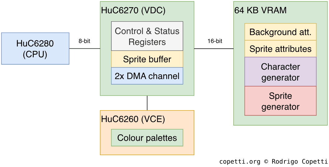
Graphics are managed by the Hudson Soft HuC6270, a separate chip also referred to as the Video Display Controller or ‘VDC’. The HuC6270 draws everything that the player sees on the screen, and its functionality is very similar to Sega’s counterpart. For this article, I will focus on the unique aspects of Hudson’s offering.
Organising the content
First things first, the VDC is a tile engine (a standard feature until the 5th generation showed up) - but note that the PC Engine includes 64 KB of Video RAM (VRAM), which is a significant amount compared to the competition. This may lead to new types of content, which we will explore later.
Memory architecture of the VDC.
The arrangement of graphics data can be somewhat confusing: both the CPU and VDC use 16-bit addresses, but while the CPU can only handle 8-bit words, the HuC6270 stores 16-bit words in VRAM [4]. This means that a single address in RAM stores one byte, whereas an address in VRAM stores two bytes. Developers therefore needed to account for this discrepancy when transferring data to VRAM.
The reason for this lies in the way Hudson organised the circuitry: The VDC has a 16-bit address bus, but only the first 15 lines are controlled (the last one is always set to 0), meaning odd addresses are fetched from the second byte. I am unsure why Hudson went down this path, but it would make more sense if the system had 128 KB of VRAM instead (since a 16-bit address bus can only access up to 64 KB, doubling the data bus could allow up to 128 KB to be retrieved). Perhaps this was the original plan for Hudson/NEC?
Constructing the frame
Aside from the aforementioned granularity oddity, the VDC is functionally straightforward. The subsystem has three main components: The VDC and VRAM, which we already discussed, and the Video Colour Encoder (also called ‘VCE’; we will examine it in due course).
The system supports multiple resolutions; this is because the game can modify a set of registers that act as parameters for controlling the display timings, which in turn alter the CRT’s scan timings. The minimum resolution is 256 × 224 pixels[5], while some homebrew projects have demonstrated that this system can achieve resolutions as high as 512 × 240 pixels.
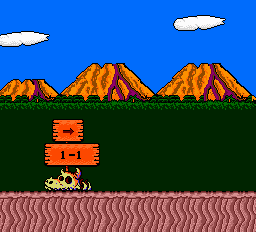
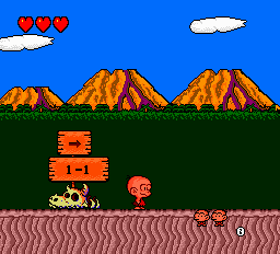
Now, let’s see how a frame is drawn step by step. For this, I will borrow assets from Bonk’s Adventure.
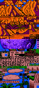
Background tiles.Sprite tiles.The two types of tiles found in VRAM.
As a quick reminder, tiles are simply 8x8 pixel bitmaps that the renderer fetches to draw portions of the screen. With the VDC, the frame is composed of two planes: the background layer and the sprite layer.
Inside VRAM, there is an area called Character generator, where tiles exclusive to the background layer are defined. Each pixel of a tile occupies four bits, allowing to use up to 16 colours. In theory, up to 4096 background tiles can be defined, but this is reduced in practice due to VRAM being much smaller.
Sprites, on the other hand, are drawn using tiles from a separate memory location in VRAM. This is called Sprite Generator and differs from the previous Character generator, as tiles here are 16x16 pixels wide.
The video encoder is a separate chip that stores 32 colour palettes (16 for the background and 16 for sprites) [6]. Each palette stores 16 colours, and each colour is 9 bits wide (3 bits for Red, 3 bits for Green, and 3 bits for Blue).
Structure of a single Background tile.Structure of a single Sprite tile.How tiles are structured in VRAM.
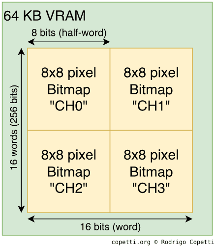
(This section is written for those interested in how Hudson leveraged the 64 KB of VRAM with its 16-bit granularity, but you don’t need to fully understand it to follow the rest of the article).
So far, we have discussed that each pixel of a tile is stored using 4 bits (or half a byte, also called a nibble). Now, Hudson dictates that tiles are encoded as four 8x8 bitmaps (called ‘CH0’, ‘CH1’, ‘CH2’, and ‘CH3’, respectively). Each map is 1-bit wide, but when the four are combined, they form the final tile with 4-bit pixels.
Due to the 16-bit alignment, each 16-bit word stores a single row of two 1-bit bitmaps (8 rows + 8 rows). So, writing eight entries results in two maps being stored (instead of just one). Please have a look at the diagrams for a clearer understanding.
The same applies to Sprite tiles, but since they are 16x16 bitmaps, each bitmap occupies 16 words. To put it another way, storing a single sprite tile requires 64 words (resulting in 8 bytes from VRAM).
The background layer is constructed by filling the Background Attribute Table with entries in VRAM. The position of each entry defines the X/Y coordinates of the tile on the screen. Each entry contains the tile index from the Character Generator and the colour palette.
The maximum dimension of this layer is 1024 x 512 pixels (128 x 64 tiles), but programmers can configure a 256 x 256 pixels (32 x 32 tiles) layer as the minimum.
As always, this layer is scrollable by changing particular registers in the VDC.
The VDC contains an internal memory called Sprite Attribute Table Buffer, where up to 64 sprites can be defined. Each entry in the table stores the independent X/Y position, colour palette, tile index, and horizontal/vertical flip. Furthermore, there is an attribute that allows to combine a sprite with another.
Each entry is 8 bytes long, although some space is wasted due to the 16-bit granularity.
To top it all off, the CPU can’t access this table, so it must be completed in VRAM first and then transferred to the VDC via a Direct Memory Access (DMA) channel.
Regarding limitations, only up to 16 sprites can appear per scan-line. On the other hand, interrupts can be configured to notify the game in case of sprite overflow or collision.
Until now, we have seen how the VDC performs most of the heavy work, but the final task is actually delegated to the Video Colour Encoder or ‘VCE’. Found on the motherboard as the HuC6260 chip, its primary function is to receive 9-bit data streams from the VDC, apply the colour palettes, and send the result to the TV as an analogue signal.
If you have read previous articles, you may be familiar with the importance of timing. This case is no exception: to avoid unwanted artefacts (such as ‘snow’), the VCE can only be updated during a vertical interrupt.
The video encoder outputs RGB (along with Sync) and YPbPr, which is ideal for use with a SCART cable or component cable, respectively. This looks promising so far…
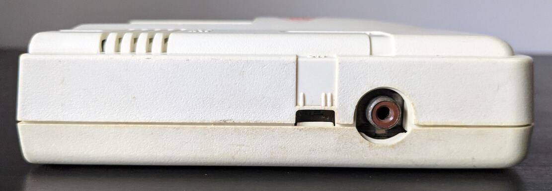
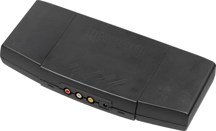
RF port at the right side of the PC Engine.The ‘Turbo Booster’ for the TurboGrafx-16 [7], connected to the Expansion port to supply video composite and power.
… Unfortunately, Hudson decided to fit an RF modulator as the only way to get video out-of-the-box, so it’s not that great after all. But then again, the PC Engine was designed in the 80s, so this approach guaranteed compatibility with most TVs of the same region.
On the bright side, the ‘Expansion Port’ exposes pins that carry RGB video and multiple sync types, but an external accessory is required to take advantage of them.
Audio
The PC Engine contains a Programmable Sound Generator or ‘PSG’, like many other third-generation consoles analysed on this website. However, this PSG particularly relies on the waveform memory (also called ‘waveform buffer’) approach to synthesise sound, rather than using a predefined set of waveforms (e.g., pulse, triangle, etc.). Waveform memory enables programmers to define their own waveforms, which gives greater flexibility for soundtrack arrangements.
Oscilloscope display during a game of R-Type (1987).
The system features six audio channels[8], each of which is configured by writing to a set of registers. These store the attributes of the channels, including:
Waveform shape: The waveform cycle is generated using thirty-two 5-bit values, each corresponding to the amplitude of the wave at a specific time.
Some games, such as Fire Pro Wrestling 2 and Bloody Wolf, even altered these values during playback to obtain unique sounds (at the expense of audible clicks during transfers).
Frequency control: Two 8-bit registers adjust the frequency of the channel to produce different musical notes using the same waveform.
Amplitude level: A single 8-bit register stores two 4-bit values that determine the volume of the channel. These values correspond to the ‘Left’ and ‘Right’ panning control, a pioneering feature compared to what the competition offered.
Extra functions
Some groups of channels have additional modes of operation. For instance, the last two channels are connected to a noise generator. Moreover, the second channel can act as a Low-Frequency Oscillator (LFO) to modulate the first channel. I initially assumed this to be a synonym for FM synthesis, but LFOs are more of a ‘subset’ that produce a vibrato effect.
Speaking of modes, there’s another one available called Direct D/A (DDA), which enables the CPU to write directly to the audio buffer (bypassing the PSG). Consequently, the PC Engine can play Pulse-Code Modulation (PCM) samples, which are still 5-bit and tightly dependent on CPU cycles. Nevertheless, two channels can be combined to reproduce 10-bit samples! [9].
All in all, this makes the PC Engine’s PSG an exceptionally flexible piece of hardware.
Final sound
The PSG mixes all audio channels and outputs a stereo signal. But again, unless you find a way to bypass the RF port, you will only hear mono audio from your telly.
I/O
This console supported a wide range of accessories, some of which completely revamped its internal capabilities (by providing more RAM, for instance) and external functionality (e.g., by adding more ports or additional storage media).
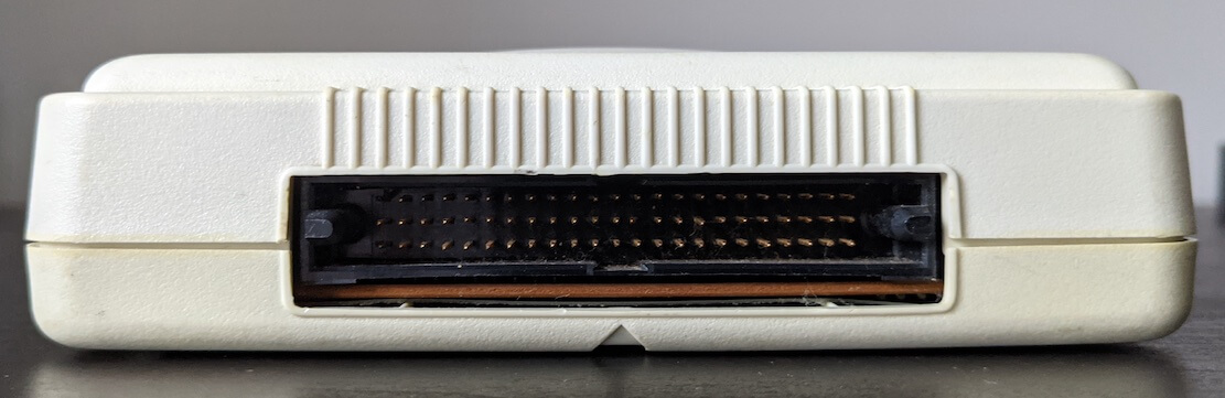
The Expansion Port at the back of the PC Engine.
This was largely due to the inclusion of the Expansion Port at the back of the console, which gave access to the following components [10]:
A +5 Volts line to power the accessory.
A Voltage input line to bypass the original PSU and power the console through the accessory.
The Audio Input and Output buses, allowing to send and/or receive stereo audio.
The CPU data and address lines, enabling the CPU to access the accessory and vice versa.
The VDC data lines, allowing the accessory to tap into the video encoder’s input. I’m not sure what for though.
The CPU control lines. These expose miscellaneous information, such as the HuCard, a CD detection flag, the speed mode used, and various interrupt lines.
The Analogue video out, including RGB + Vertical Sync and Horizontal Sync + Composite sync.
I’m curious to know the extent to which NEC or Hudson envisioned this console. Were they attempting to build some sort of ‘modular console’ that could be upgraded to seamlessly transition into the next generation?
The rest
I have yet to mention the controller (or Joypad, as some sources call it). It is very similar to other offerings. The console provides only one controller port, and games check a single address in memory to retrieve key presses. That address returns a 4-bit value [11].
Operating System
There is no internal ROM, ‘Basic Input/Output System’ (BIOS) or any other software that runs before the game, meaning the console does not have an Operating System. The reset vector is located at addresses $FFFE and $FFFF (remember that the internal registers are 8-bit, but memory addresses are 16-bit, requiring two words to initialise the program counter). These addresses point to the game card [12].
This also means that it is the programmer’s responsibility to handle ‘housekeeping’ (e.g., initialising memory, setting up the MMU, and so on).
Games
Programs are written in 6502 assembly, spiced with extra 65C02 opcodes and the custom instructions introduced by Hudson.
Standard Medium
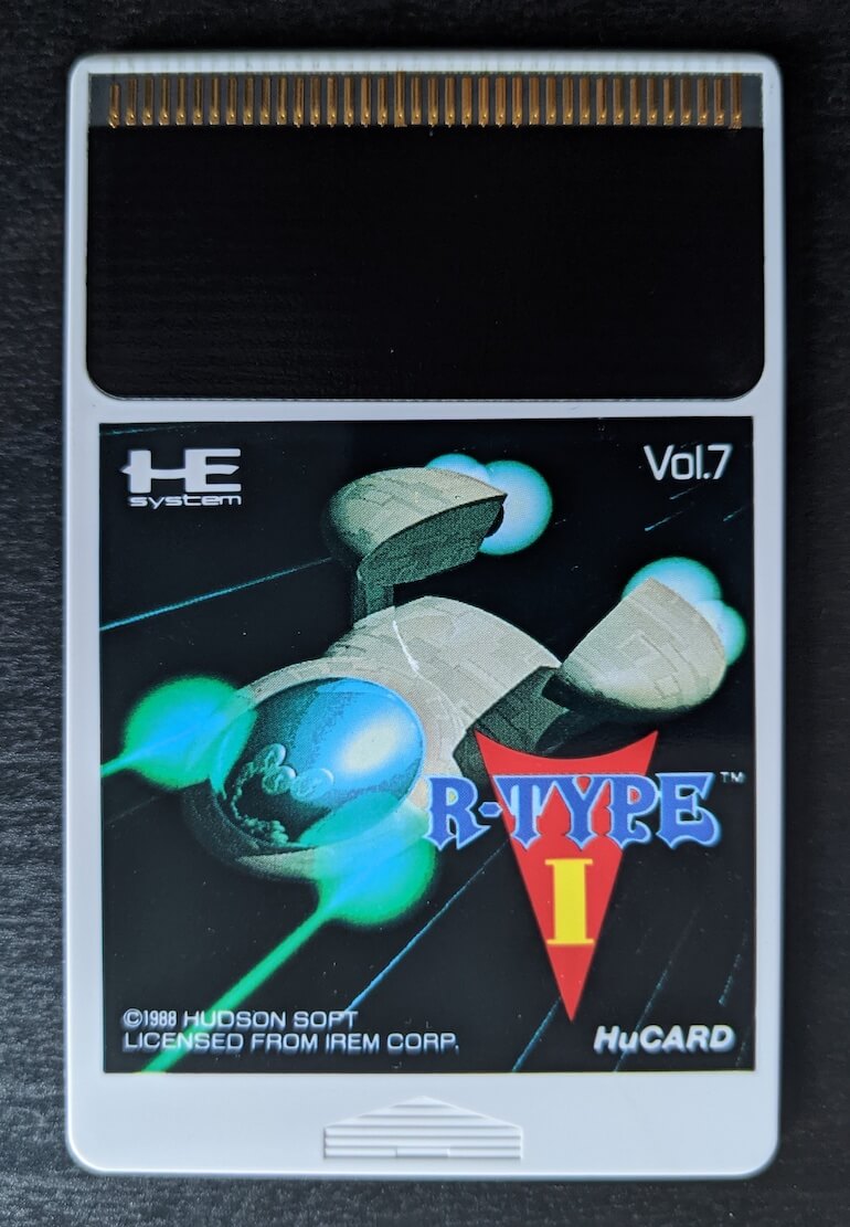
Instead of relying on those chunky and boring cartridges everyone else seems to like, NEC and Hudson devised a new medium, this time with the size of a credit card, called HuCard. It was derived from an older medium called ‘Bee Card’, used in some MSX games.
Typical retail game.
Interestingly, they are very similar to the Sega Card, featuring 38 pins instead of 35 [13]. Internally, however, the differences are more significant:
The CPU memory map can access up to 1 MB of HuCard memory without a mapper, which is why the majority of games were limited to 1 MB ROMs. Even so, games like ‘Street Fighter II’ resided in a 2.5 MB ROM! [14]
There is an Audio In pin, which apparently allows the card to supply an extra audio channel.
CD-ROM Expansion
That expansion port opened the door to a wide range of accessories and expansion units, eventually transforming the simple PC Engine into something entirely different. As if that wasn’t enough, the HuCard slot also complemented the possibilities of expansion. For this article, I will focus on the most notable upgrades, some of which were incorporated into later revisions of the console.
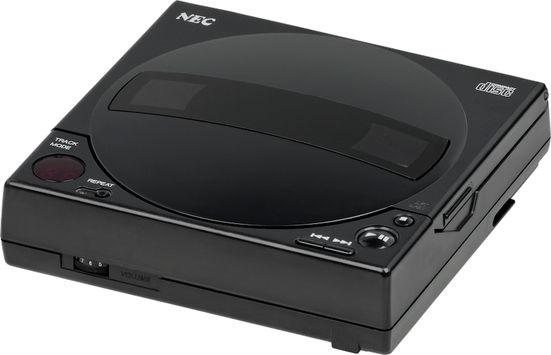
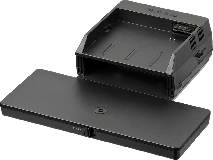
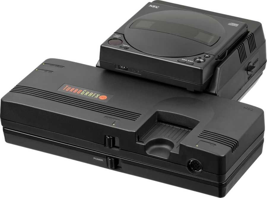
CD-ROM² Reader (TurboGrafx-16 version) [15]. Were they in the Discman business back then?Base required to connect the console to the reader [16]. It also supplies power and composite video out.How it looked with everything fitted [17].
Let’s take a look at the CD-ROM² expansion, which consists of a CD-ROM reader and a special HuCard called the System Card. The latter acts as a BIOS to bootstrap the game and provide routines to interface with the reader. Internally, the CD-ROM reader included 64 KB of RAM for general-purpose use, another 64 KB of RAM for streaming ADPCM samples, and 2 KB for save data. As you can guess, this enabled game developers to take advantage of extra storage and CD audio, while providing publishers with the economic benefit of distributing games on a popular medium.
Years later, NEC released another CD module called the Super CD-ROM². While the reader’s hardware remained mostly unchanged, its general-purpose RAM was increased to 256 KB. Customers that already owned a CD-ROM² unit could ‘upgrade’ it by purchasing the Super System Card, which included the additional RAM (and one more I/O routine!). On top of all that, NEC later shipped BIOS updates in the form of the Arcade Card, which now housed 2 MB of RAM.
CD-based games relied strictly on the BIOS card they were developed for, although newer cards were backwards compatible (with some exceptions). Thus, the Arcade Card became the preferred choice for users who wanted to play almost all CD-ROM-based games. I say ‘almost’ because third-party companies also released their own BIOS cards (e.g., the ‘Games Express CD Card’), which were required to play games specifically from those studios.
With the Super CD-ROM², NEC and Hudson also shipped a new variant of the PC-Engine/TurboGrafx-16 called the Turbo Duo, which bundled the console, reader and BIOS card into a single package.
More expansions
If you are curious about other expansions, I recommend checking out the online catalogue [18].
Anti-Piracy and Homebrew
HuCards are region-locked, meaning that a PC-Engine game will not work on a TurboGrafx-16 (or vice versa) without modification. This is because the order of the data lines is inverted on the American version. However, as you can guess, this isn’t something a cheap adapter can’t tackle. That said, games may include routines to verify the system’s region.
In contrast, CD-ROM games are neither region-locked nor copy-protected, but they still require a System Card to bootstrap, and the card itself is region-locked.
That’s all folks
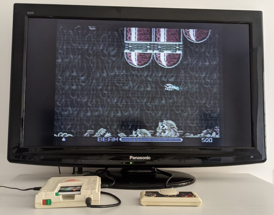
My PC Engine connected with the RF cable (nostalgic purposes… I think). Big thanks to Matt for donating it!
You have reached the final article of the year!
2020 has been an ‘eventful’ year for the website (setting aside the many challenges that have affected all of us). The year began with the Wii article and carried on with the PS2, Xbox, Nintendo DS, Master System, and finally, this one.
The number of visitors has grown significantly too. It had a slow start at first, but during the summer, there was a remarkable increase in traffic. I would like to thank Hacker News users, OSNews, Reddit, Gigazine, YouTubers, Twitter users and many other forums and individuals for sharing the articles. And of course, a big shout-out goes to the donors whose generosity has helped keep the site afloat!
Have a nice Christmas, a Happy New Year 2021, and until next time! Rodrigo
Contributing
This article is part of the Architecture of Consoles series. If you found it interesting then please consider donating. Your contribution will be used to fund the purchase of tools and resources that will help me to improve the quality of existing articles and upcoming ones.
You can also buy the book editions in English. I treat profits as donations.
Big thanks to the following people for their donation:
- Carlos Diaz Navarro
- Colin Szechy
- David Portillo
- Duncan Bayne
- Eric Haskins
- Grady Haynes
- Josh Enders
- Olivier Cahagne
- Samuel Shieh
- Sanqui
- Thomas Peter Berntsen
This work is licensed under a Creative Commons Attribution 4.0 International License. You may use it for your work at no cost, even for commercial purposes. But you have to respect the license and reference the article properly. Please take a look at the following guidelines and permissions:
Article information and referencing
For any referencing style, you can use the following information:
Title of article: PC Engine / TurboGrafx-16 Architecture - A Practical Analysis
I only ask that you at least state the author’s name, the title of the article and the URL of the article, using any style of choice.
You don’t have to include all the information in the same place if it’s not feasible. For instance, if you use the article’s imagery in a Youtube video, you may state either the author’s name or URL of the article at the bottom of the image, and then include the complete reference in the video description. In other words, for any resource used from this website, let your viewers know where it originates from.
This is a very nice example because the channel shows this website directly and their viewers know where to find it. In fact, I was so impressed with their content and commentary that I gave them an interview 🙂.
Appreciated additions
If this article has significantly contributed to your work, I would appreciate it if you could dedicate an acknowledgement section, just like I do with the people and communities that helped me.
This is of course optional and beyond the requirements of the CC license, but I think it’s a nice detail that makes us, the random authors on the net, feel part of something bigger.
Third-party publishing
If you are interested in publishing this article on a third-party website, please get in touch.
If you have translated an article and wish to publish it on a third-party website, I tend to be open about it, but please contact me first.
It’s always nice to keep a record of changes. For a complete report, you can check the commit log. Alternatively, here’s a simplified list:
### 2025-05-11
- Overall improvements to prepare for a book release.
- Extra photography.
### 2022-06-25
- Corrected LFO mention, thanks @Stakker (see https://github.com/flipacholas/Architecture-of-consoles/issues/96)
### 2022-06-15
- Corrected MMU address line numbers, thanks @pppq (see https://github.com/flipacholas/Architecture-of-consoles/issues/101) and Chris Dew
### 2021-04-28
- Added mention to DDA playback and waveform altering at runtime (see https://github.com/flipacholas/Architecture-of-consoles/issues/18), thanks @khaliewicz### 2020-12-18
- Publishing date?
### 2020-12-16
- First draft finished.
- Thanks @dpt for checking out the draft.
- Carlos, R-type is very hard.
Rodrigo Copetti
I hope you have enjoyed this article! If you want to know more about the author tap here and if you would like to support him tap here instead