This article is also published in many bookstores for the benefit of offline readers. The eBooks are DRM-free, while the printed editions compile multiple articles and feature original photography at full resolution.
You can find printed compilations here, and individual eBooks at Amazon Kindle, Apple Books, Kobo and other stores. The proceeds support the improvement of current articles and the development of new ones.
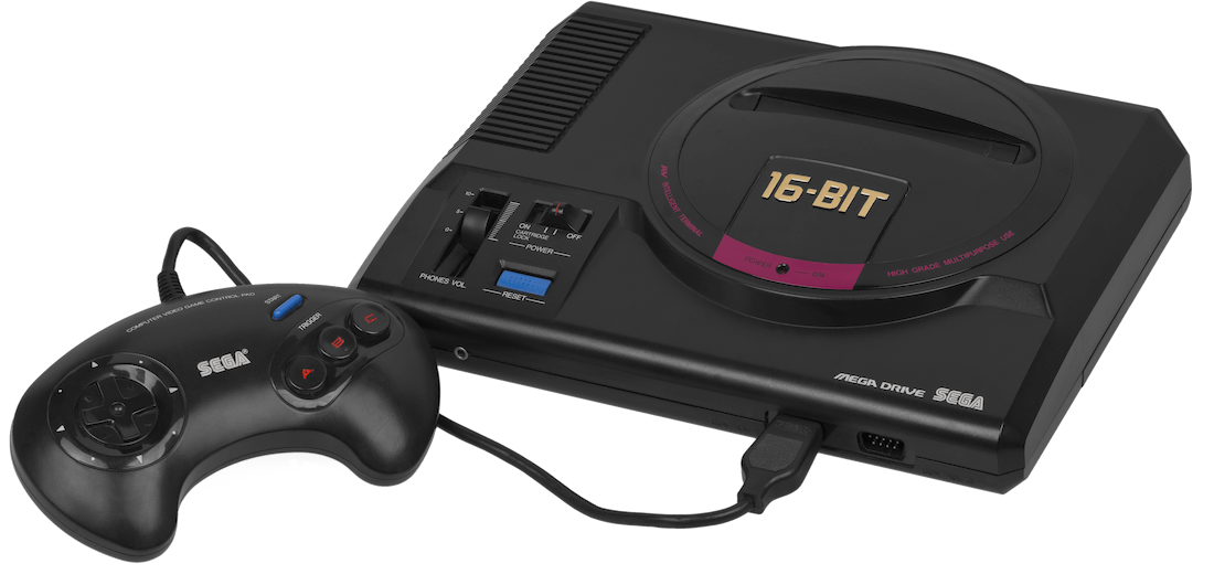
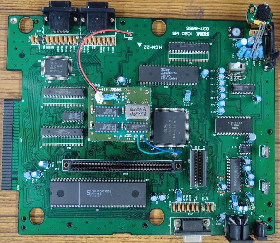
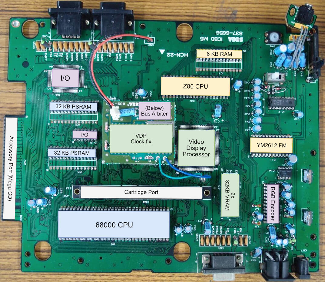
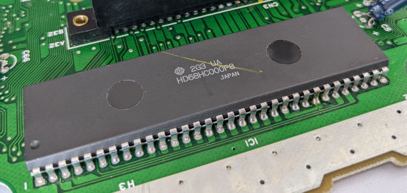
Motherboard Showing the Japanese 'VA0' revision. Notice the unusual daughterboard on top of the VDP used to fix post-manufacturing glitches (properly corrected in later revisions).Motherboard with important parts labelled
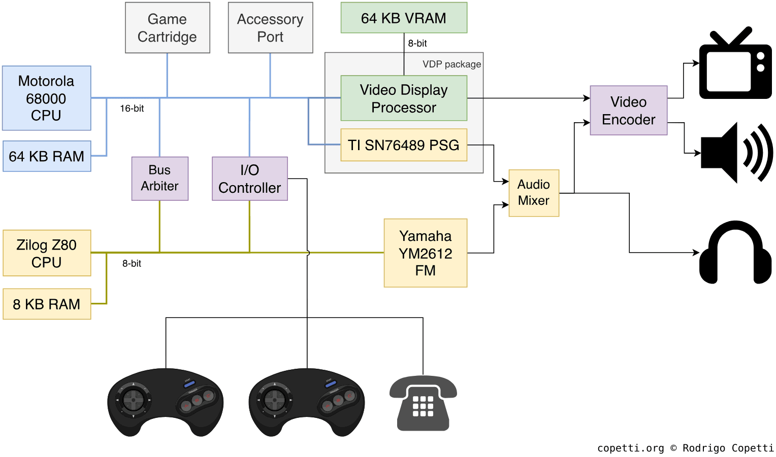
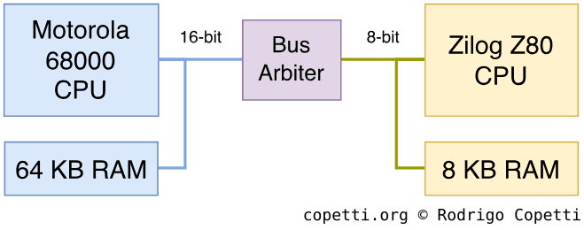
DiagramMain architecture diagram
A quick introduction
Sega (and their TV ads) want you to know: Developers can’t come up with decent games unless the console provides faster graphics and richer sounds.
Their new system includes lots of already familiar components ready to be programmed. This means that, in theory, developers would only need to learn about Sega’s new GPU… right?
CPU
This console features two general-purpose processors from two distinct generations.
The leader
Firstly, we’ve got a Motorola 68000 running at ~7.6MHz. This is a new class of CPU which deserves a bit of story-telling…
Powering a decade
The Motorola 68000 or ‘68k’ served as a generational leap in the history of microprocessors. Having learnt from the mistakes of the 6800, the company started over with a new team that could offer an affordable door to the 32-bit space. In there, much larger chunks of data could be processed, enabling programmers to provide new capabilities previously unknown to the consumer.
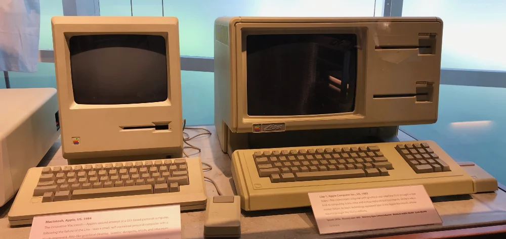
Apple’s Macintosh (1984) and Lisa (1983). While at very different price points, both relied on the Motorola 68000 to display their innovative user interface.
Released in 1979, the 68k arrived in time to power the next decade of microcomputers. While initially struggling after losing IBM’s contract to Intel, it didn’t take long until other companies and start-ups adopted this chip to power their new inventions. Some implemented incremental improvements over their predecessors, while others achieved unthinkable capabilities, to name a few:
A Graphical User Interface (GUI). New 68k-based products from Amiga, Apple, Atari and Sinclair debuted a novel form of user interaction. This time, founded on iconography, shapes and colours - and controlled with a ‘Mouse’.
Workstation applications: These cost-effective machines were now capable of processing huge workloads, with some degree of specialisation. This led to the rise of networking infrastructure, graphics design and research equipment - among others.
This also coincided with the arrival of UNIX-based operating systems to the masses, leading to an uneasy proliferation of ‘standards’ and subsequent lawsuits.
It’s worth pointing out that much of this functionality wasn’t new - it had simply been reserved for the costly minicomputers or prohibitive mainframes. The milestone lies in the fact that all of this could now be accessed from the typical office or household.
The Motorola 68000 chip on the Mega Drive, this one is second-sourced from Hitachi.
By the end of the 80s, however, interest in the 68000 faded in favour of a new wave of RISC CPUs. Yet, prices had come down enough for companies like Sega to take an interest in bringing it to the console market.
Features
Having set the scene, let me tell you what the 68000 provides [1]:
The 68000 Instruction Set Architecture (ISA): A new instruction set with plenty of features, including a set of multiplication and division opcodes. Some instructions are 8-bit long (called ‘byte’), others are 16-bit long (called ‘word’) and the rest are 32-bit long (called ‘long-word’).
Sixteen general-purpose 32-bit registers. Bear in mind, this CPU splits the set into eight ‘data registers’ (where arithmetic computations may be performed) and eight ‘address registers’ (exclusively used for storing memory addresses).
Nevertheless, this is a big step, considering the 6502 and Z80 only provide 8-bit registers.
A 16-bit Arithmetic Logic Unit (ALU): Meaning it needs extra cycles to compute arithmetic operations on 32-bit numbers, but it’s fine on 16-bit/8-bit ones.
An external 16-bit data bus: As you can see, while this CPU has some ‘32-bit capabilities’, it hasn’t been designed to be a complete 32-bit machine. The width of this bus implies better performance when moving 16-bit data around.
Interestingly enough, Motorola debuted a complete 32-bit CPU, the 68020, four years before this console’s release. But I imagine costs would’ve skyrocketed had Sega chosen the latter chip.
A 24-bit address bus: This means that up to 16 MB of memory can be accessed. Memory addresses are still encoded with 32-bit values inside the CPU (the upper byte is just discarded).
If you wonder the reason behind using 24-bit addresses in a CPU that can handle 32-bit words: the equipment of that era was hardly asking to manage 4 GB of memory. Given that implementing unused lines is costly in terms of both performance and money, Motorola reached a sensible compromise with 32-bit registers and 24 address lines, preparing developers for the arrival of the full 32-bit CPU (the 68020) five years later.
A peculiar instruction set
Before the RISC revolution, there was a prior school of thought that attempted to consolidate how instruction sets were designed. In essence, consumer CPUs of the 70s (like the 6502 or the 8080) provide instructions that have already predefined how memory can be accessed (this is called the ‘addressing mode’). A choice of multiple addressing modes enables the CPU to handle different use cases. However, the number of addressing modes tends to proportionally increment the complexity of the instruction set.
To remedy this, with the 68000, Motorola sought to unify most of its instructions. It did so by detaching the instruction function (the ‘opcode’) from the addressing mode, making the latter just another parameter (or ‘operand’). In doing so, developers could now use the same opcodes with their addressing mode of choice (based on their needs).
As a simple example, to move data around:
The MOS 6502 and WDC 65816 offer LDA, STA, LDX, STX, LDY, and STY opcodes. The choice depends on the direction of information (whether from register to memory or vice versa) and the specific register involved.
Additionally, in the WDC 65816, the parameter specifying the size of data (8-bit or 16-bit) resides in a separate register, requiring additional instructions (SEP and REP) to change it.
In contrast, the Motorola 68000 provides a single MOVE opcode; its operands specify the origin, destination, size and addressing type.
This principle is called instruction set orthogonality, and it greatly influenced the new generation of CPUs in the late 70s, but quickly dissipated as RISC designs took over, effectively shifting the burden onto compilers. In any case, the Motorola 68k series enjoyed great popularity during the 80s decade, and it wasn’t until the early ’90s that companies started the switch to another vendor.
The Mega Drive’s role
Within this console, the 68k serves as the ‘main’ CPU and it’s tasked with managing game logic, handling I/O and performing graphics calculations.
Consequently, the external bus is physically connected to [2]:
64 KB of general-purpose RAM.
Cartridge ROM (up to 4 MB).
Two Controllers.
The Video Display Processor’s registers, ports and DMA.
Motherboard’s registers (identifies the console).
Expansion ports (used for ‘future’ accessories).
The second CPU’s RAM, intermediated by a bus arbiter.
The Texas Instruments SN76489 (a PSG, acting as the second sound chip).
The second banana
There’s another CPU fitted in this console: a Zilog Z80 running at ~3.5 MHz. This is the same processor previously analysed in the Master System article.
With the Mega Drive, however, the Z80 was mainly designated for sound control. Thus, its 16-bit address space comprises the following [3]:
8 KB of RAM.
The two sound chips available.
A dynamic chunk of 32 KB mapped to the 68000’s address space, selectable via a ‘bus arbiter’.
In practice, however, the only reliable area to access here is the cartridge ROM [4].
Finally, it’s important to note that both CPUs can run in parallel… under certain constraints, the next paragraphs explain more.
Memory available
The main CPU contains 64 KB of dedicated RAM to store general-purpose data and the Z80 contains 8 KB of RAM for sound-related operations.
Intercommunication
Sega chose two independent processors that have no awareness of each other, so how can games manage both at the same time? Well, the main program is executed on the 68000, and this CPU can subsequently write to the Z80’s RAM. So, the 68000 can send a program to the Z80’s RAM and instruct the Z80 to load it (by sending a reset signal to the Z80) [5]. Once the Z80 is under control, it can then be used to manage the sound subsystem and move memory around using the previously described method - all while the 68000 handles other operations.
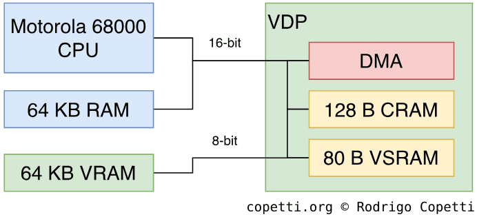
Memory architecture of the Mega Drive/Genesis.
There is one caveat, however: because one CPU must step into the other’s bus, both CPUs cannot access the same bus at the same time. To address this, an extra component called Bus Arbiter is operated to stall either processor, enabling memory manipulation without any hazards.
It’s worth noting that this design can underperform if not managed properly, so games have to take special care of the bus arbiter to ensure that neither CPU is stalled for longer than necessary.
Graphics
The answer is Blast Processing! What else do you need to know?
Okay, if you want to know the real answer: graphics data is processed by the 68000 and rendered on a proprietary chip called Video Display Processor (or ‘VDP’ for short), which then sends the resulting frame (in the form of scan lines) for display.
The VDP runs at ~13 MHz and supports multiple resolution modes depending on the region: up to 320x224 pixels in NTSC and up to 320x240 pixels in PAL.
Behind the multiple display resolutions
Technically speaking, the VDP can fit either 40 or 32 columns of tiles per scan-line, and the number of tile rows depends on the region (28 in NTSC or 30 in PAL) [6]. Although, most PAL games do not bother with the extra tiles allowed in PAL systems (as they probably need to keep consistency between the two regions, and NTSC is the common denominator) so they instruct the VDP to render with 28 rows (as in NTSC systems). Thus, the VDP has no option but to fill the unused area with a backdrop colour (also used during overscan).
You can identify which PAL games render in NTSC mode by checking the Mode Set Register #2 in an emulator with debugging capabilities (e.g., Exodus). If the fourth bit from the right is 0, the VDP is running in NTSC mode [7].
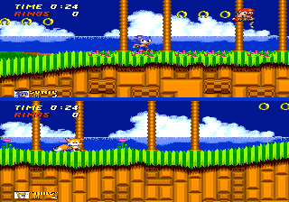
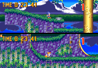
To provide a quick multiplayer mode in Sonic 2 (1992), the game activates ‘interlaced mode’ to render a single-player level using 8x16 pixel tiles instead (along with other changes).By contrast, the more sophisticated multiplayer mode of Sonic 3 (1994) relies on dedicated 8x8 pixel tiles that are separate from single-player levels.
Furthermore, there’s an additional parameter that can be set on the VDP to stack two tiles to form 8x16 maps and then treat them as a single tile. Hence, doubling the vertical resolution. However, this halves the refresh rate as frames are now rendered with interlacing (one frame renders even scan-lines, the next beams odd ones, and so forth) so it’s more limited in terms of functionality. The multiplayer mode of Sonic 2 is a good representation of this mode [8].
Finally, it’s worth pointing out that the VDP automatically takes care of adding padding for the overscan area, so games don’t have to worry about which areas are safe to draw graphics into (as it happened with the NES’ ‘danger zones’).
Organising the content
In terms of processing the graphics data, this chip has two modes of operation:
Mode IV: The legacy mode that behaves like its predecessor.
This doesn’t mean this console will play Master System games right away, as an additional accessory, the Power Base Converter, is required to fit previous cartridges into this console. The converter also instructs the I/O chip to place the Z80 in control.
Mode V: The native mode of operation. We’ll focus on this one.
What about Modes 0 to III? Well, these belong to the even older SG-1000 and the Mega Drive does not support them.
As an interesting note, a former developer of this system told me that the command structure of Mode V (used to control the VDP) inherits the design from the TMS9918, the well-known video chip used in the SG-1000 [9]. This made it easier for third-party developers to operate Mode V without relying on official documentation (and subsequent licensing costs).
Memory available
Memory architecture of the VDP.
The graphics content is distributed across three regions of memory [10]:
64 KB VRAM (Video RAM): Contains most of the graphics data.
80 B VSRAM (Vertical Scroll RAM): The VDP supports vertical and horizontal scrolling; and V-scroll values are stored in this separate space, for some reason.
128 B CRAM (Colour RAM): Stores four palette entries with 16 colours each (including transparent), the system provides 512 colours to choose from. Additionally, Highlight and Shadow effects can be applied to each palette to achieve a wider range of colours per palette.
Constructing the frame
The following section explains how the VDP draws each frame. For demonstration purposes, Sonic The Hedgehog is used as an example. Before proceeding, I recommend checking out the modus operandi of its predecessor since a lot will be revisited here.
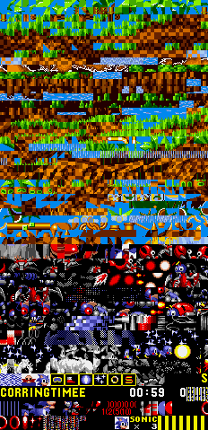
Multiple tiles squashed together. For demonstration purposes, a default palette is being used.A single 8x8 pixel tile.Some tiles found in VRAM.
Just like Nintendo’s PPU, the VDP is a tile-based engine, and as such, it uses tiles (basic 8x8 bitmaps) to compose graphic planes. In the case of the VDP, each tile is encoded with a 4-byte-long array, where each 4-bit entry corresponds to a pixel and its value corresponds to a colour entry (pointing to a colour palette).
Game cartridges store tiles in their ROM (found in their cartridge) but these must be copied to VRAM for the VDP to read them [11]. Traditionally, this was only possible during specific time frames and handled by the CPU, fortunately, this console added special circuitry to offload this task to the VDP (we’ll get into details later on).
Tiles are used to construct a total of four planes, which, when merged, form the frame seen on the screen. Additionally, the tiles in these planes can overlap with each other, so the VDP determines which tile is visible based on the type of plane and the tile’s priority value.
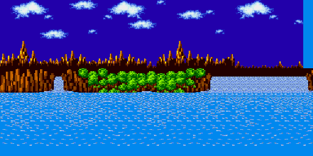
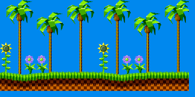
Allocated Background map.Allocated Background map with selected area marked.Example of Background plane.
The Background plane, also known as Plane B, is a scrollable tilemap (set of tiles) containing static tiles[12].
This plane supports six different dimensions: 256x256, 256x512, 256x1024, 512x256, 512x512, and 1024x256. Programmers may select the dimension that best suits the required scrolling type.
Each tile can be flipped horizontally and/or vertically and have a priority set.
In the example shown, you will notice that the selected area for display is not a square… It doesn’t have to be!. The VDP allows to set up horizontal scrolling values for the whole frame, each individual scan-line or every eight pixels. This means that developers can shape the selected area like a rhomboid and alter its angles as the player moves to simulate perspective effects. Tricks like this do not corrupt the plane; the VDP fetches each selected horizontal line and constructs a regular frame from it.
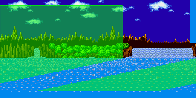
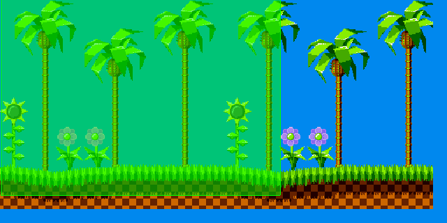
Allocated Foreground plane.Allocated Foreground plane with selected area marked.Example of Foreground plane, the Window Plane is not used.
The Foreground plane, also known as Plane A[13], shares the same properties as the Background Plane except this plane has a higher priority, meaning tiles rendered here will always be on top of the Background Plane.
Additionally, this plane can divide itself to form a new sub-plane: The Window Plane. The only difference is that the latter doesn’t scroll.
All in all, you can see the new priority values and separate planes enable game designers to bring new types of scenery. Furthermore, by using different scroll speeds on each plane, a parallax effect can be achieved.
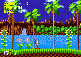
Allocated Sprite layer.Allocated Sprite layer with selected area marked.
In this plane, tiles are treated as sprites. They are positioned on a 512x512 pixel map and only a portion of it (the VDP’s output resolution) is selected for display. This is convenient for hiding unwanted sprites or preparing others that will be shown in the future. The VDP also provides an old collision detection function.
Sprites are formed by combining up to 4x4 tiles (32x32 pixel map) and selecting up to 16 colours (including transparent). If a bigger sprite is needed, multiple sprites can be combined into one.
There can only be a maximum of 20 sprites per scan-line and 80 per screen. Overflowing these limits will corrupt the entire layer.
The region in VRAM where sprites are defined is called Sprite Attribute Table[14] and each entry contains the tile index, layer coordinates (x and y), link value (manages which sprites are drawn first), priority (the sprite with the highest priority is the one to be displayed during overlaps), colour palette index, and vertical and horizontal flip.
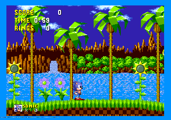
Resulting frame.Frame broadcasted to the TV (in NTSC format). The VDP automatically adds an overscan area, which most CRT TVs will hide.Tada!CRAM dots in the bottom-left corner of the overscan area.
While the frame is being drawn, the system sequentially calls different interrupt routines based on the position of the CRT’s beam. As you have probably seen in previous consoles, this allows the CPU to prepare the next frame (or alter the current one).
Conventionally, two types of interrupts are called: H-Blank (at every horizontal line) and V-Blank (at the end of each frame).
H-Blank is called numerous times per frame, but is limited to executing short routines. V-Blank, on the other hand, allows for longer routines, with the drawback of only being called 50 or 60 times per second (depending on the console’s region).
Notice that the overscan area in the example exhibits some random coloured dots in the bottom-left corner. This phenomenon, known as CRAM dots, occurs when the CPU updates the palettes in CRAM while the VDP is beaming the remaining scan-lines (in the example, this happens during overscan). This conflict causes the VDP to fetch whatever value the CPU is writing at that moment, rather than the required location in CRAM. So, the image gets corrupted. In this particular case, the game updates CRAM only during overscan, so this anomaly goes unnoticed on traditional CRTs. At another level in the game, however, the game changes the palette mid-frame to simulate water effects. Hence, programmers tried to mask it by drawing a flickering water ripple in-between [15]. As you can see, it’s all about balancing the extra colours with the CRAM side-effect.
So far we’ve discussed what the CPU can do to update frames, but what about the VDP? Does it provide something more specialised? Well yes, this chip features a Direct Memory Access (‘DMA’ for short) that allows moving data between memory locations at a faster rate and without the intervention of the CPU.
The DMA can be activated during H-Blank, V-Blank, or active state (outside any interrupt) and can be used to write over VRAM, CRAM, and/or VSRAM [16]. However, during CPU RAM transfers using DMA, the CPU bus is blocked, so careful planning is critical for achieving performance.
Effective use of these features may enable high-resolution graphics, smooth parallax scrolling, and high frame rates. In the best cases, your game might even be featured in TV ads with lots of Blast Processing! signs over it.
Video Output
The first design of this console (commonly referred to as the ‘Model 1’) includes the same video out port as the Master System. The subsequent ‘Model 2’ and ‘Model 3’ revisions switched to a mini-DIN port.
Audio
The audio capabilities of this console are somewhat unorthodox, to say the least. On one side, the Mega Drive incorporates audio technology from the previous generation. On the other hand, it introduces a novel (yet complex) synthesis technique. So, in some ways, you get two generations in a single console.
That being said, the Mega Drive is equipped with two sound chips: A Yamaha YM2612 and a Texas Instruments SN76489.
Functionality
Let’s now see what each chip offers, as they are very different.
FM channels.PCM channel.Sonic The Hedgehog (1991).
The Yamaha YM2612 is an FM synthesiser[17] that provides six FM channels, one of which can play Pulse-Code Modulation (PCM) samples instead. It operates at one-sixth of the 68000’s clock speed and outputs one channel at a time, but it alternates between each channel every four cycles to create the illusion of generating all six channels at once [18]. For this reason, the Yamaha YM2612’s sampling rate is ~53 kHz. Furthermore, it accepts PCM samples with a resolution of nine bits[19]. Yet, the ninth bit was never officially documented so commercial games only sent 8-bit samples. Apart from that, its bus is connected exclusively to the Z80.
Frequency Modulation (FM) synthesis is one of many professional techniques used for producing sound. It significantly rose in popularity during the 80s and made way to completely new sounds, many of which you can find by listening to the pop hits from that era (I would give you a list but my music taste is a bit experimental).
In an incredibly simplified nutshell, the FM algorithm takes a single waveform (carrier) and alters its frequency using another waveform (modulator). The result is a new waveform with a different sound. The carrier-modulator combination is called operator and multiple operators can be chained together to form the final waveform. Different combinations achieve different results. The YM2612 allows four operators per channel.
Compared to traditional PSG synthesisers, this was a drastic improvement: You were no longer stuck with predefined waveforms.
The Texas Instruments SN76489 is a Programmable Sound Generator (PSG) capable of producing three pulse waves and one noise channel.
This is actually the original sound chip from the Master System, now embedded within the VDP. It runs at the speed of the Z80.
Programming the PSG involves writing to a single 8-bit location (called PSG port[20]), and both CPUs can do so. Behind the scenes, its bus is connected only to the 68000, but the Bus Arbiter seamlessly manages access when the Z80 writes to it.
Notice in this example, the ‘Pulse 3’ channel remains muted. This is because the game activates a mode that reserves the third pulse for modulating the noise channel [21], a function featured on the Master System as well.
The Z80 is an independent processor by itself, so it needs its own program (stored in the 8 KB of available RAM) to interpret the music data received from the 68000 or the cartridge ROM and effectively manipulate the two sound chips accordingly. This program is referred to as a sequencer or driver.
Nevertheless, the design of a sound driver is not completely dependent on the Z80 CPU. While the Z80’s memory map suggests that this is the only processor capable of commanding the two audio chips in unison (which may be a relief for the 68000, as it is already fed up with other tasks), the Bus Arbiter can still shut down the Z80 to grant the 68000 access to the YM2612 [22]. This is not as efficient but it’s still another option for programmers to consider. For instance, the first Sonic The Hedgehog implemented its sound driver on the 68000, whereas later entries offloaded this task to the Z80 [23].
Cracking sampling
Rather than sticking with ordinary drum kits, there have been occasions where music composers pushed the PCM channel to produce more natural sounds. Since this could only be implemented through software, games had to continuously sequence and stream their music without exceeding the Z80’s limits. The main constraint was that, to fill its RAM during sequencing, the main bus had to be blocked first (preventing commands or samples from being sent to the audio chips during that timeframe). Otherwise, sound anomalies such as muting, frozen notes, or low sample rates could appear.
While an unaffordable challenge at first, certain games overcame this with the help of creative techniques. For instance, Traveller’s Tales’ Toy Story (1995) allocated the 68000 for sequencing the music [24]. This was a highly intensive task, meaning it could only be executed at very particular points of the game, such as the main menu.
PCM channel.All audio channels.Oscilloscope view of Sonic The Hedgehog 3 (1994). Its soundtrack was rumoured to have been co-authored by Michael Jackson.
While one can argue it’s still miles ahead from achieving CD-quality (16-bit at 44.1 kHz), the advancements made compared to its predecessors certainly deserve recognition. And it is always this type of skill what pushes the boundaries of music in the next generation of consoles.
Assisted FM Composition
Programming an FM synthesiser was already considered complicated using the Yamaha DX7’s dashboard - now imagine the headaches of composing music with only 68k/Z80 assembly…
Fortunately, Sega later distributed a piece of software for MS-DOS PCs called GEMS to simplify the composition (and debugging) of Mega Drive music [25]. This comprehensive tool included numerous patches (pre-configured operators) to choose from, which may explain why some games have very similar sounds.
Moreover, their audio driver enabled games to instantiate more channels than the hardware allowed. With the use of priority values, the console played the music by dynamically dispatching channels to the available slots. Additionally, channels with high priority but no music were automatically skipped.
Channels also incorporated some logic by embedding conditionals within their data, allowing music to ‘evolve’ based on the player’s progress in the game.
(Bonus) Mega CD Sound
Here is an interesting fact, the Mega CD add-on provided two extra channels for Audio CD (among other things). One of its most famous games, Sonic CD, featured very impressive compositions but, like all games, it had to loop. The problem was that looping tracks on a 1x CD reader exposed noticeable gaps. So, the game included loop fillers that were executed from another PCM chip while the CD head was returning to the start.
For some reason, these fillers are only found on early betas of the game and they didn’t make it for the release. However, the 2011 remake finally included them.
MegaCD version (1993).Remastered version (2011).
Games
Games are primarily written in 68000 assembly, while the sound driver is implemented in Z80 assembly. Both reside in the cartridge ROM and can be up to 4 MB in size without the need for a mapper.
Extra functions
In terms of expandability, this design wasn’t as modular as the NES or the SNES. Hence, later add-ons like the 32x (which included a new chipset that took over the 68k) had to bypass the VDP, necessitating the use of a ‘Connector Cable’.
Only one custom chip was produced for cartridges: the Sega Virtua Processor (SVP) [26], a rebranded Samsung SSP1601 (itself a 16-bit Digital Signal Processor). The new chip produced polygons that were subsequently encoded as tiles for the VDP to read. In any case, only one game shipped with it, as the SVP proved too expensive to manufacture.
Early network attempts
Before online services became widely adopted and standardised, Sega tried its luck with Sega Meganet, a dial-up service for games to use. Meganet required users to purchase a separate accessory called the Sega Mega Modem, plug it to the back of the console (where the DE-9 connector is), and finally connect it to the phone line. Games treated the modem unit as another controller, with the addition of communicating with it serially [27] (as opposed to the parallel encoding used for controllers).
Be that as it may, this feature only lasted a couple of years before Sega removed the DE-9 connector in later revisions and discontinued the service entirely.
Anti-piracy / Region Lock
To block imported games, Sega slightly altered the shape of the cartridge slot between regions, although it kept the same pinouts. Games could also perform ‘region locking’ by checking the value of the Version register, which outputs the console’s region code.
There were two simple ways to bypass this: purchasing a third-party cartridge converter or disassembling the console and bridging the pins on the motherboard to alter the value of the Version register.
When it comes to software anti-piracy measures, the easiest check involved verifying the SRAM size. Bootleg cartridges often bundled more space than needed to fit any title, so games checked for the expected size during startup. Programmers could also implement extra checksum checks at random points in the game to counteract attempts to bypass the initial SRAM checks. The only way to defeat this was to painstakingly find all the checks and remove them one by one…
That’s all folks
Contributing
This article is part of the Architecture of Consoles series. If you found it interesting then please consider donating. Your contribution will be used to fund the purchase of tools and resources that will help me to improve the quality of existing articles and upcoming ones.
You can also buy the book editions in English. I treat profits as donations.
A list of desirable tools and latest acquisitions for this article are tracked in here:
### Interesting hardware to get (ordered by priority)

- 32X (£ ?)
- Any dev kit (only if found at a reasonable price)

### Acquired tools used

- PAL Mega Drive with a Mega CD and a couple of games (£150)
- Switchless region free mod (£20, the desoldering tools were much more expensive!)
- Component video adapter (£30)
This work is licensed under a Creative Commons Attribution 4.0 International License. You may use it for your work at no cost, even for commercial purposes. But you have to respect the license and reference the article properly. Please take a look at the following guidelines and permissions:
Article information and referencing
For any referencing style, you can use the following information:
Title of article: Mega Drive / Genesis Architecture - A Practical Analysis
I only ask that you at least state the author’s name, the title of the article and the URL of the article, using any style of choice.
You don’t have to include all the information in the same place if it’s not feasible. For instance, if you use the article’s imagery in a Youtube video, you may state either the author’s name or URL of the article at the bottom of the image, and then include the complete reference in the video description. In other words, for any resource used from this website, let your viewers know where it originates from.
This is a very nice example because the channel shows this website directly and their viewers know where to find it. In fact, I was so impressed with their content and commentary that I gave them an interview 🙂.
Appreciated additions
If this article has significantly contributed to your work, I would appreciate it if you could dedicate an acknowledgement section, just like I do with the people and communities that helped me.
This is of course optional and beyond the requirements of the CC license, but I think it’s a nice detail that makes us, the random authors on the net, feel part of something bigger.
Third-party publishing
If you are interested in publishing this article on a third-party website, please get in touch.
If you have translated an article and wish to publish it on a third-party website, I tend to be open about it, but please contact me first.
It’s always nice to keep a record of changes. For a complete report, you can check the commit log. Alternatively, here’s a simplified list:
### 2025-04-21
- Multiple corrections, see https://github.com/flipacholas/Architecture-of-consoles/issues/400 (thanks @Clownacy).
### 2024-01-31
- Added information about the orthogonal instruction set.
### 2022-12-17
- Added visual examples about interlaced mode and removed wrong examples. See https://github.com/flipacholas/Architecture-of-consoles/issues/163 (thanks @Mittens0407)
### 2022-01-12
- Corrected statement about the pulse 3 (see https://github.com/flipacholas/Architecture-of-consoles/issues/86), thanks @Ralakimus### 2021-11-27
- Updated game screenshots and graphic materials.
- Added diagrams.
- General grammar and spelling fixes, with some re-phrasing in-between.
- Added information about accessing the YM2612 through the 68000 and the command structure of Mode V (see https://github.com/flipacholas/Architecture-of-consoles/issues/54), thanks @djmips.
- Added info about CRAM dots and MegaNet.
- Improve referencing style.
### 2020-10-25
- Added more content focusing on the 68k-z80 communication
### 2020-09-07
- Expanded CPU section
- Corrected main RAM values
### 2020-01-18
- Expanded Audio section and included more audible content
### 2019-09-17
- Added a quick introduction
### 2019-05-23
- Improved definition of FM (such a difficult topic)
### 2019-05-18
- Ready for publication
Rodrigo Copetti
I hope you have enjoyed this article! If you want to know more about the author tap here and if you would like to support him tap here instead